
The machine uses a ‘grbl’ controller, which has an Arduino-based circuit that includes multiple outputs, including a powerful 24V pwm signal that is generally used to drive a 60-80W spindle motor.
Replacing that motor in this case is a brushless dc motor with its own three-phase drive box that can be controlled with a 5V pwm waveform or a 0-5V analogue voltage – It has its own 0V and 5V outputs which, due to long leads and high currents, are only loosely related to the 0V and 5V on the Arduino.
Opto-isolation is the obvious answer (until TI’s non-opto-isolators are easier to get) to remove ground voltage variations, and that got me thinking about adding a few components to the input side of an opto-isolator to make it suitable for all of a grbl controllers output pwms, and useful in many other situations.
In general, the many commercially-available grbl controller boards have:
- Two-pin 24V + 0V multi-amp pwm output for directly driving a brushed dc motor
- Two pin 12V + 0V multi-amp pwm for directly driving a laser module
- Three pin 12Vdc (multi-amp) + 0V + 5V logic signal for driving other laser modules
- Possibly a direct 5V pwm signal from the ATmega MCU output (that can provide >16mA)
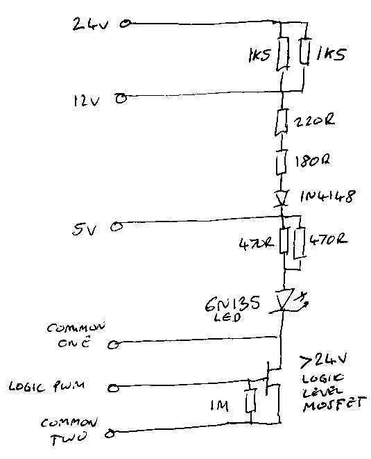
The circuit on the left can interface with any one of those, plus any 5V logic signal if a dc voltage of 5, 12 or 24V is also available.
16mA has been chosen for the led current to match the drive needs of a 6N135 opto-coupler – a fast (nominally 1Mbit/s 2MHz) device with equal rise and fall times if the right output resistor and voltage are chosen.
In many cases, a slower and lower-current opto-coupler would be fine, but this design is intended to maintain timing precision over a wide range of input frequencies to make it useful in more situations.
To use it for any 5V, 12V or 24V PWM signal that can provide at least 16mA, connect between the appropriate input and Common One (ignore Common Two and Logic PWM).
To use with a logic pwm signal (any logic voltage matching the mosfet) you also need a power rail of 5, 12 or 24Vdc that shares a common with the logic.
Connect the power rail between the appropriate voltage input and Common Two, and connect the logic signal between Logic PWM and Common Two (ignore Common One).
Notes:
- Resistor are doubled in some places to get the current (obsessively!) correct, and share power dissipation – the 1k5 resistors might have to deal with ~100mW each, the 220R around 60mW and the 180R around 50mW.
- The 1N4148 adds a measure of reverse polarity protection – the 6N135 led is rated to withstand 5V reverse polarity.
- The 1M resistor is to hold the mosfet off when the gate is open-circuit – to reduce the chances of the spindle motor leaping into life due to 50Hz pick-up if the gate is not connected, for example. Safety note for the unwary: Electric motors can be dangerous, and means must be provided to prevent them springing into life unexpectedly. This circuit does not provide such protection.
- When using the mosfet, an interference-suppression capacitor might be useful between Common Two and whichever dc rail input is being used.